Flare Strut System
Technical Info
Flare Strut
Technical Info
All-Thread Rod
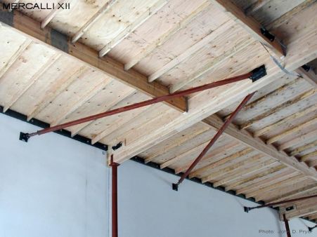
The Flare Strut system was designed and developed for retrofit wall anchorage applications in tilt-up buildings, and provides significant capacity and performance advantages over conventional interconnected timber framed dragline wall anchorage systems. The system typically consists of a Flare Strut with an EC1 End Connection attached to the wall panel with either a Crab Anchor or plated anchor, and an EC2 End Connection with a Screw Plate that is attached to the glulam beam. The Flare Strut can also be used in many other types of applications as well.
Flare Strut features include the following:
- Direct Connection: The Flare Strut provides for a direct connection between the wall panel and the glulam beam.
- Sub-diaphragm Eliminated: The sub-diaphragm is eliminated as part of the wall anchorage system. Issues regarding sub-diaphragm capacity are eliminated. This eliminates the need to remove and replace roofing in order to provide retrofit sub-diaphragm nailing, or nailing into the timber elements of conventional dragline wall anchorage systems. Issues regarding potential roof leaks and voided roofing warranties are eliminated.
- Insulation and Finishes: Eliminates the need to remove and replace insulation and/or finishes, as can occur with conventional timber framed dragline wall anchorage systems.
- Articulation: Three axis rotational articulation allows the end connections to mount flush to any surface at any orientation. Problems with skewed walls and glulam beams are eliminated.
- Field Adjustable: The Flare Strut design allows for the location of the end connections to be field adjusted to avoid interference problems, as may occur with wall reinforcing, piping, conduits, and ducts.
- Length Adjustment: The high tolerance threads associated with the coupler-pipe element of the strut element provide for fast fit-up and installation, while also allowing for 3" of overall length adjustment
- End Connections: The EC1 connection attaches to the wall panel with either an exterior plate, through bolt, and shear plate, or a Crab Anchor, with 4 - ½" epoxy anchors. The EC2 end connection attaches to the glulam beam with a Screw Plate (and SDS screws) and a through bolt.
- Minimum Set-up Locations: Installation of a paired Flare Strut only requires three set-up locations, one for each of the EC1 end connections at the wall panel, and one at the glulam beam for both of the EC2 end connections. This minimizes potential problems that can occur when access restrictions exist.
- Field Fabrication: Contractor is required to field cut and drill the EC2 end of the strut element. This is typically done with a portable band saw or a dry cut-off saw, and a magnetic base drill.
- Paired Installations: For typical retrofit wall anchorage applications Flare Struts are intended to be installed in pairs. For non-paired Flare Strut installations, the transverse loading to the glulam beam needs to be considered, addressed, and resolved.
- Steel Beams and Plate Girders: For Flare Strut installations with steel beams and plate girders, the EC2 end connections can be directly attached to the webs of these members.
- Bi-directional Load Capacity: The Flare Strut is designed to resist loads in both tension and compression.
- Capacity: Maximum capacity of a typical TS3x3x3/16 strut element is 24,800 lbs in tension and 10,500 lbs in compression (ASI = 1.33, L = 18.83'). These capacities are generally more that adequate for most wall anchorage installations. Note that the actual capacity of a Flare Strut installation can be limited by other elements of the system, such as the wall anchor (plated or epoxy), screw plate, or end connections. As needed, Flare Struts with other strut element shapes or sizes, and capacities are available.
For more information, load tables, design information, installation guidlines, and cad drawings, please contact Mercalli XII.
Flare Strut System
The Flare Strut system was designed and developed for retrofit wall anchorage applications in tilt-up buildings, and provides significant capacity and performance advantages over conventional interconnected timber framed dragline wall anchorage systems.
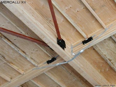
Flare Strut End Connections
The system typically consists of a Flare Strut with an EC1 End Connection attached to the wall panel with either a Crab Anchor or plated anchor, and an EC2 End Connection with a Screw Plate that is attached to the glulam beam.
The Flare Strut can also be used in many other types of applications as well.
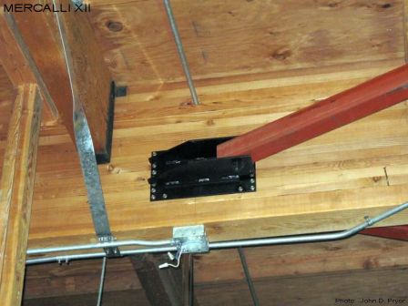
Flare Strut EC2A
This is a closer look at the End Connection at the GluLam beam, the EC2A.