Various Conditions 3
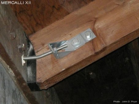
M12-EX-1181
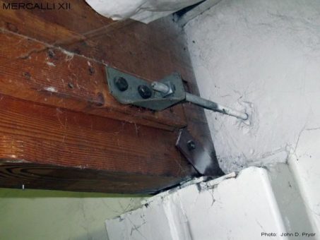
A purlin wall tie installation with a single sided clip angle. It would appear that bolt attaching the clip angle to the ledger bolt has only been partially threaded into the coupler. This could have been avoided if padding had been installed between the purlin and clip angle so as to better align the bolt with the coupler. This would have required longer bolts, which were probably not available when this installation was completed. As such, the bolt is likely to pull out of the coupler when loaded, rendering this wall tie installation completely useless.
M12-EX-1191
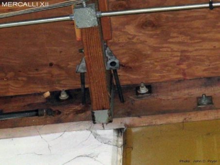
A purlin wall tie installation with paired HD2's. Note that the anchor on the right has been installed into the joint between the two wall panels, and will be useless. As such, the capacity of this wall tie will be significantly reduced. When such installations are encountered, one must question whether or not the design engineer addressed this condition in the original structural plans for the building, whether or not the contractor that completed this installation thought to bring this situation to the attention of the design engineer, and whether or not this installation was approved by an inspector?
M12-EX-1201
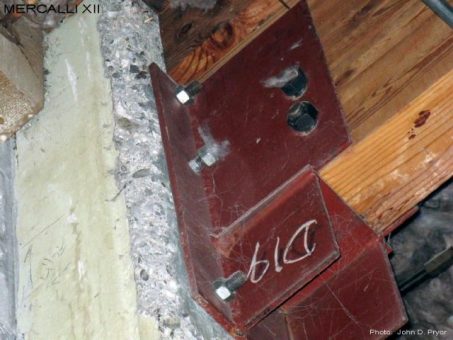
A glulam bracket at a pilaster. Note that both of the the nuts associated with the glulam through bolts are loose, as well as the nut associated with one of the anchor bolts. As it would seem that it would be pretty easy to be able to tighten these nuts when they were installed, it brings into question everything else that might have been completed by the contractor that had installed this glulam bracket.
M12-EX-1211
A glulam wall tie with a single sided HD2 padded out with a 2x4 that has been nailed to the glulam beam. Note that the glulam beam is supported by a split pilaster. Split pilasters consist of two partial pilasters that are cast with the wall panels, are not interconnected, except by possibly a chord bar splice near the roof line. Since this is only a single sided wall tie, out-of-plane loads from the wall panel on the other side of the glulam beam must be taken through the anchor associated with the glulam beam support bracket, and the single through bolt attaching the support bracket to the glulam beam. In light of the current design requirements and standards for such installations (taking into account the additional design loading caused by the pilasters and flexibility of the HD2) this existing glulam wall tie would now be considered grossly inadequate.
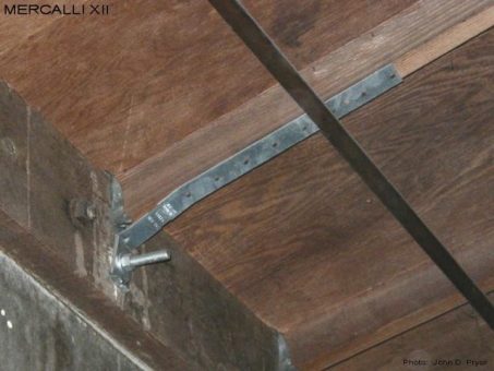
M12-EX-1221
A purlin wall tie installation with paired HD5A's in an older panelized tilt-up building with roof trusses. Due to the slope of the purlins, the allthread rod has been bent to allow the epoxy anchors to be installed horizontally into the wall panel. When loaded, this bend will subject the base of the HD5A to a transverse load, which the HD5A is not necessarily designed to resist. As an alternate, the epoxy anchor could have been installed at a slope to match that of the purlin, which would have eliminated this problem, and allowed for a greater embedment into the wall panel. It should also be noted that due to the manner in which allthread rod is manufactured, it can be much less ductile than one would expect (such as that required per ASTM A36), and should not be bent.
M12-EX-1222
An LTT19 strap tie attached to the bottom of a 2x4 sub-purlin in an older panelized tilt-up building with roof trusses. Due to the flexibility of strap and holdown type connectors, some building jurisdictions, such as the City of Los Angles (COLA), have imposed deformation requirements with regard to establishing their allowable design capacities. The COLA criteria limits the allowable capacity of a connector used in wall anchorage assemblies to the average 1/8" deflection load when tested on a steel test jig divided by 3. Due to this requirement, the allowable capacity of strap and holdown type connectors has been significantly reduced, and has reduced the capacity of the LTT19 shown above from 1205 lbs to 508 lbs (a 58 percent reduction).
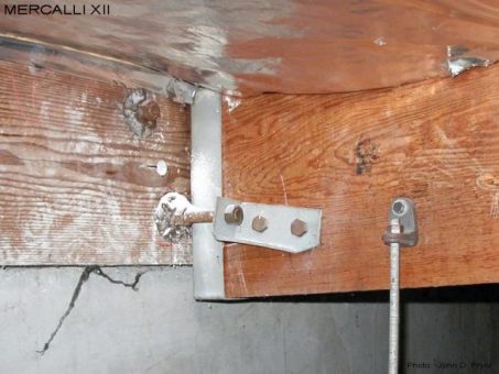
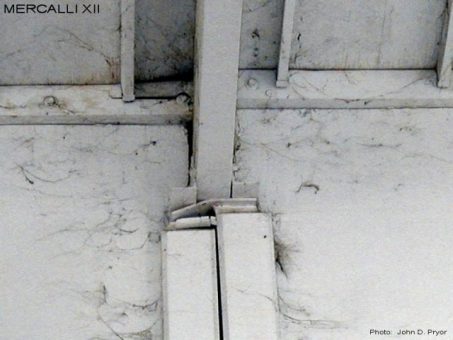
M12-EX-1231
A purlin wall tie installation with paired HD2 holdowns. The skew of the HD2 shown would indicate that the connection was drilled from the opposite side of the purlin, and that the bolt holes were not drilled straight or accurately. Not being able to drill straight and accurate bolt holes can be a significant problem, especially for holdowns with more that two bolts, and can lead to back-drilled and oversized bolt holes. Minimizing deformations is very important with regard to the performance of a wall anchorage installations. Oversized bolt holes will increase the deformation a wall anchorage installation will undergo when loaded, and greatly reduce it's effectiveness. The use of drill guides can greatly mitigate this problem, and should be required for all paired connections.
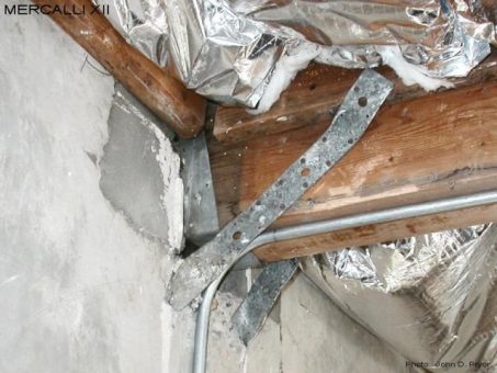
M12-EX-1241
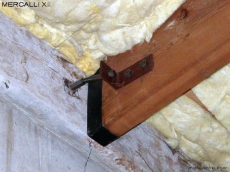
A purlin projects into a support pocket at an outwards projecting pilaster. The two straps projecting up from the top of the pilaster appear to have been hammered on a bit, and have been nailed to both the purlin as well as the 2x framing attached to the purlin. Due to the vertical skew of the straps, this connection is expected to see some significant deformations when loaded, and not expected to perform well.
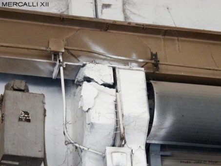
M12-EX-1251
A glulam beam supported on a split pilaster. As can be seen, some significant differential settlement has occurred between the two wall panels associated with each half of the split pilaster. This has damaged the ledger, the glulam beam seat bracket, and most likely the chord bar splice (if present) interconnecting the two panels at the roofline. Differential movement between independent wall panels can occur during an earthquake if one or both panels goes into a rocking mode, with the resulting damage similar to that shown above. This can compromise the connection between the glulam beam and split pilaster, which in turn can lead to the collapse of the glulam beam. When the potential for such a situation exists, measures should be taken to interconnect the two wall panels, and prevent such differential movement from occurring.
M12-EX-1252
Lower down on the same split pilaster shown in the previous photo. As can be seen, the crane rail appears to have won the battle with the support corbel on the left side of the split pilaster. The differential settlement between the two wall panels appears to be approximately 2".
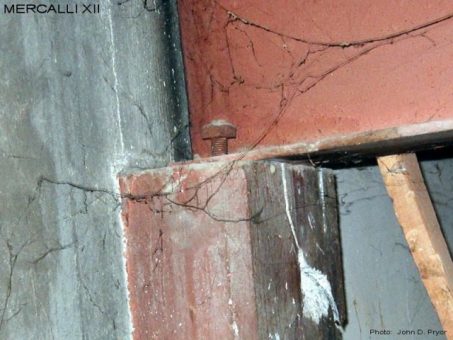
M12-EX-1261
An un-tightened nut at the top of a pilaster supporting a steel beam. It would appear that the threads have been damaged, and the contractor completing this installation didn't want to take the time to correct the situation. Also note that the concrete at the top of this pilaster is cracked. This was noted at a few other locations at this building.
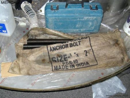
M12-EX-1291
Black althread rod in a burlap bag with "Made in India" on it. It's anyones guess is to what specification this allthread rod was made to, if any. This was not a Mercalli XII project!

