Various Conditions 1
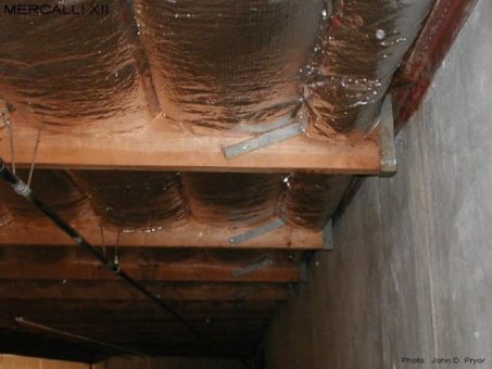
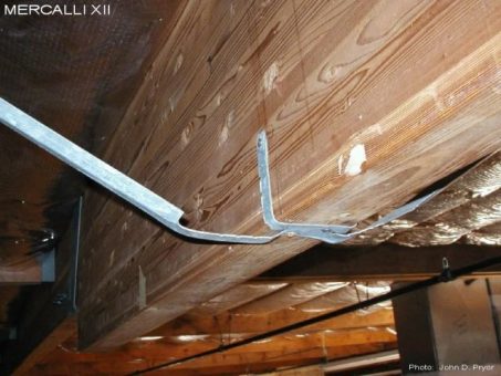
M12-EX-1091
A line of purlins supported on a steel angle ledger. The steel angle ledger eliminates the cross grain bending problems typical of wood ledgers. The paired strap ties shown are nailed to the purlin with 1/4" diameter N54 nails, and welded to the angle ledger. When loaded, the inclination of these strap ties will create a vertical force component that may cause the purlins to lift out of their support hangers. The inclination of these straps should have been minimized in order to mitigate this potential problem.
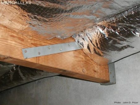
M12-EX-1092
A close up of one of the purlin wall ties shown in the previous photo. The 1/4" diameter N54 nails used to attach the straps to the purlin can be be quite a chore to install when being hammered into green lumber, and almost impossible when installing them in older framing that is hard and dry, without pre-drilling first. We now tend to recommend and use1/4" SDS screws instead of N54 nails, as the SDS screws tend to be much easier to install.
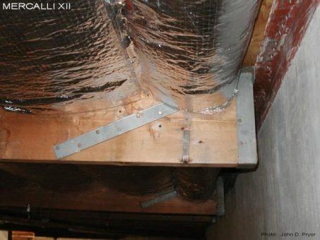
M12-EX-1093
Another close up of a purlin wall tie similar to that shown in the previous photo. The inclination of the strap appears to be more pronounced at this location. The steel angle ledger can be seen along with the steel drive pins attaching the plywood sheathing to the top leg of the angle ledger.
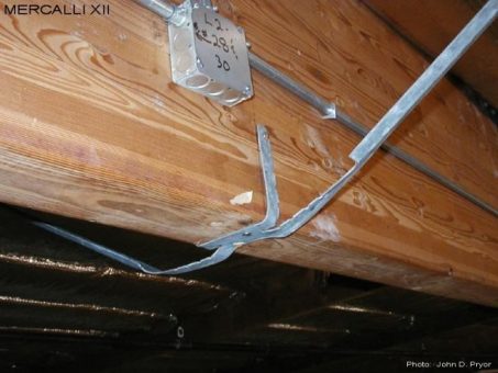
M12-EX-1094
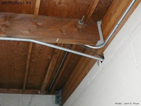
We tend to find that VB Knee Braces are installed more like the one shown above than those depicted in the manufacturers literature.
M12-EX-1095
Another perspective of the previous photo. In response to the installation problems encountered with VB Knee Braces, Mercalli XII developed an alternate Vee Strap that is pre-bent per the width of the glulam beam with the straps projecting out at an inclination of approximately 30 degrees, and uses SDS screws instead of N54 nails. This has eliminated most of the installation problems typical of VB Knee Braces. For photos of Vee Straps, see "Flare Strut - End Connections 2".
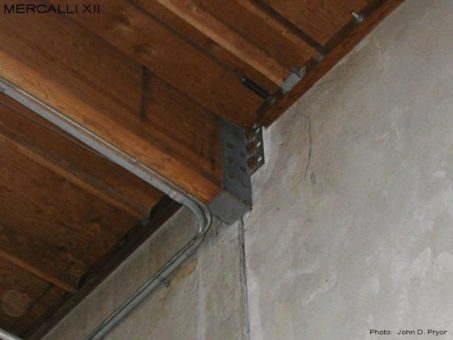
M12-EX-1101
When glulam beams are located at panel joints as shown above, the supporting bracket must span across the joint and anchor into two independent wall panels. With such installations there is always the possibility that the glulam bracket will be subjected to forces it was not originally designed to resist, which increases the potential for a bracket failure, and the collapse of a major roof framing element during an earthquake. Such forces include panel-to-panel shear forces that can be caused by panel rocking, panel-to-panel diaphragm chord forces, panel-to-panel thermal forces, and out-of-plane wall anchorage forces. Note that the anchors on the right side of the glulam bracket shown have been slotted to prevent this connection from being subjected to panel-to-panel tensile forces.
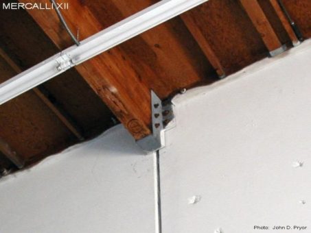
M12-EX-1102
Another photo of a glulam beam with a support bracket located at a panel joint. When brackets such as these pose the potential of a failure and a collapse threat during an earthquake, mitigation can include the installation of backup columns, and/or panel-to-panel shear restraint elements, if there is a potential panel rocking. Also note the Rod & Plate dragline at the upper right corner of the photo.
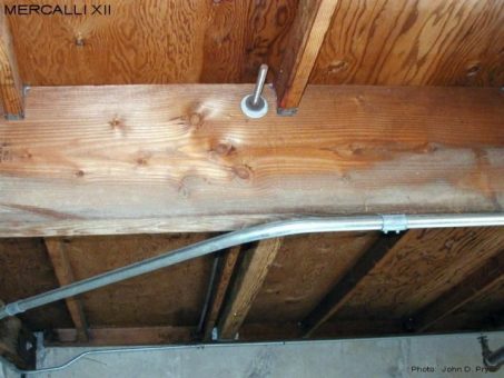
M12-EX-1103
A Rod & Plate (R&P) dragline wall tie. The rod associated with this installation appears to have been installed just above the bottom of the 2x4 sub-purlin, but only a cut washer has been used for a bearing plate. As such, the capacity of the R&P dragline will be minimal, but could have been greatly increased with the installation of a 1/4 x 3 x 3 bearing plate at a nominal additional cost (approximately $1.25 per current rates).
M12-EX-1104
Another Rod & Plate (R&P) dragline similar to that shown in the previous photo. It would appear that the 4x4 sub-purlin to the left of the rod is intended to be the compression element of the R&P dragline system. Unless the ends of the compression elements of a R&P dragline system are properly shimmed tight to the ledgers and purlins, the system can experience significant additional deformations when loaded.

