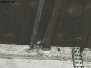
Strap Ties
M12-EX-1011
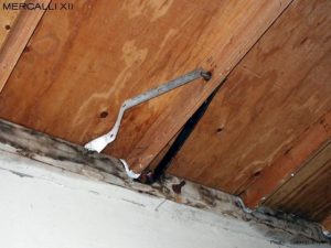
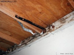
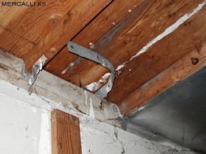
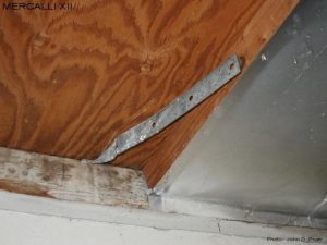
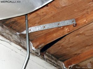
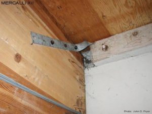
Most of the strap ties in this building were so badly misaligned that they had to be abandoned and replaced with the retrofit strap ties shown. Misaligned strap ties tend to be a recurring problem with tilt-up buildings. Corroded ledger bolts, fasteners, and water stains are an indication of past roof leaks and/or moisture problems.
M12-EX-1012
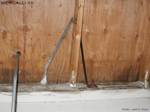
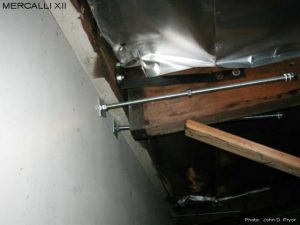
Another view of the connection shown in the previous photo. The retrofit strap tie appears to have been installed "backwards", as the ledger bolt to which it is attached is to close to the 2x4 sub-purlin to allow it to be installed "correctly" per the assumed intentions of the engineer. It also appears that the retrofit strap may be missing a bolt.
M12-EX-1013
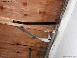
Another badly misaligned and abandoned strap tie. All of these connections were originally covered up with the silver insulation paper shown, and could not be seen. Spider webs are also an indication of roof leaks and moisture problems.
M12-EX-1014
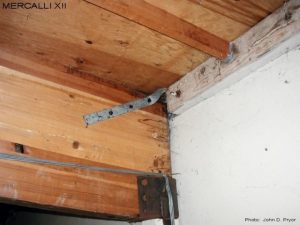
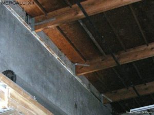
Another misaligned and abandoned strap tie. In some cases, particularly in buildings with roofs that leak, the silver insulation paper shown can cause significant moisture problems in the area between the insulation paper and the plywood sheathing.
M12-EX-1015
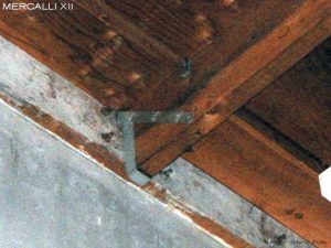
Another badly misaligned and abandoned strap tie. Note that the retrofit strap tie has been attached to a ledger bolt located about 5" from the 2x4 sub-purlin. Note the stained ledger and highly corroded ledger bolt caused by moisture trapped between the silver insulation paper (now removed) and the plywood sheathing.
M12-EX-1016
View from below of the connection shown in the previous photo. This photo shows more clearly the eccentricity between the ledger bolt and the 2x4 sub-purlin, as well as how badly the original strap tie had been misaligned. Eccentric connections, like this one, will try to twist and pull the sub-purlin towards the ledger bolt when loaded, and were found to be a problem during the 1994 Northridge earthquake. Current codes and standards now require that eccentric connections be structurally justified. As a result, most connections are now designed to be concentric.
M12-EX-1017
Another view of the connection shown in the previous two photos. Strap tie connections also tend to deform significantly when loaded. Excessive connection deformation can inadvertently subject the ledgers to cross grain bending and failures. Provisions established by the City of Los Angeles have substantially reduced the effective capacity of strap ties and other connection devices when used for wall anchorage installations in tilt-up buildings (and other buildings of similar construction) due to their flexibility.
M12-EX-1018
A single sided strap tie at a glulam beam. The end bolt appears to be missing from this installation, while the first bolt appears to lack sufficient end distance to the top of the glulam beam. Note the bend in the strap tie as it comes out of the wall panel.
M12-EX-1019
Another view of the glulam strap tie connection shown in the previous photo. In addition to the eccentricity between the glulam beam and strap tie, note the significant bend in the strap tie between the wall panel and the glulam beam. This connection would not be expected to perform well during an earthquake, as it is likely to deform significantly when loaded, and subject the ledger to cross grain bending.
M12-EX-1020
During the retrofit of this building two adjacent purlins were found to have almost come out of their hangers. In this photo, the purlin only had about 1/4" of bearing engagement with the hanger. Marks on the purlin from the hanger would indicate that the hanger had moved or been pushed back from its original location about 2.5". These purlins were quickly shored, and the hangers re-positioned to their original locations, before the installation of the purlin wall ties were completed.
M12-EX-1141
A dark photo of some varied strap tie installations. A horizontally oriented retrofit strap tie has been installed on the first purlin, while a typically installed strap tie is seen on the second purlin. The strap tie on the third purlin has been inclined so steeply that its end projects slightly below the bottom of the purlin. The literature of some manufacturers specify that such strap ties are to be installed at a maximum inclination of 2 degrees in order to develop full load capacity. The inclination of the strap tie on the second and third purlins appears to exceed the 2 degree limit.
M12-EX-1142
This strap tie should have been installed as close to the bottom of the 2x4 sub-purlin as was possible. Instead, for no apparent reason, it was installed at such a steep inclination that it extends to the bottom of the purlin. Due to this inclination, the purlin will be subject to an upwards force component during an earthquake that, if not adequately restrained, will cause the purlin to lift up, resulting in damage.
M12-EX-1143
A dark photo of a badly misaligned strap tie that was "creatively" bent in order to attach it to the 4x4 sub-purlin dragstrut element (next to the 2x4 sub-purlin). The excessive deformation or elongation this strap tie will undergo when loaded during an earthquake will essentially render this connection completely useless. Unfortunately, we find that connections like these are more common than they should be.

