Rod & Plate Draglines
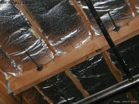
M12-EX-1111
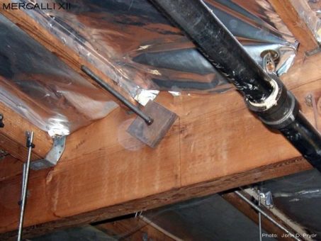
Rod and plate (R&P) dragline wall ties typically consist of a length of rod or allthread rod that is attached to the wall panel by coupling onto either a ledger bolt or anchor (epoxy, wedge, plated), and anchored off to one or more purlins with a bearing plate and nut. In order to be effective the bearing plates must be installed above the bottom of the sub-purlins, otherwise they will subject the purlin to cross grain bending, and likely to do more harm than good. Note that the bearing plates of the R&P draglines in this photo have been located below the bottom of the 2x4 sub-purlins, and will subject the purlin to cross grain bending when loaded.
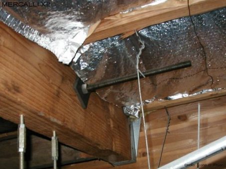
M12-EX-1112
The use of wall tie systems on timber framing elements that will cause either cross grain bending or cross grain tension has been specifically disallowed since the 1976 Uniform Building Code. Even so, in this photo the bearing plate of the R&P (rod and plate) dragline has clearly been located below the bottom of the sub-purlins, and when loaded will subject the purlin to cross grain bending. It is not known if the original design details specified that the bearing plate be located as shown, or if the contractor just decided to install them that way. In any event, this R&P wall tie would not be expected to perform well during an earthquake, and may cause additional damage to the purlin.
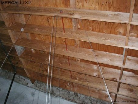
M12-EX-1121
In this photo a R&P (rod and plate) dragline has been taken out to the sixth roof joist from the wall panel as shown. When loaded this R&P dragline will subject the single roof joist to weak axis bending between the blocking either side of the rod line (with a span of approximately 8 to 10 feet). Due to the limited capacity of the roof joist in weak axis bending combined with the significant deformations this joist is likely to undergo when loaded, this R&P dragline will be relatively useless during an earthquake. As a minimum, a double line of blocking should have been installed with the rod line, and nailed off to the plywood sheathing.
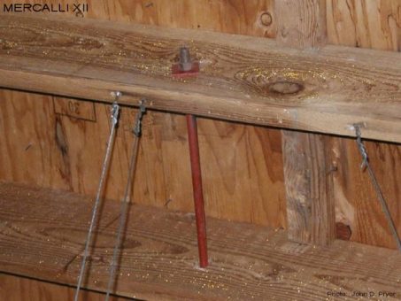
M12-EX-1122
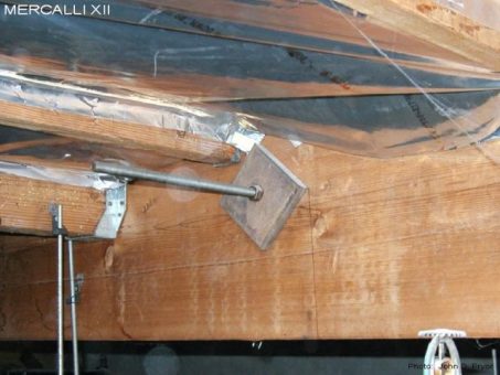
A close up of the bearing plate associated with the R&P dragline shown in the previous photo. This appears to only be a 1/4 x 2 x 2 bearing plate, and may have been adequate per the design requirements at the time the building was constructed, but quite inadequate per current design requirements. Given the nominal cost of bearing plates, it is unclear why a more substantial bearing plate was not specified in the original details for this installation.
M12-EX-1131
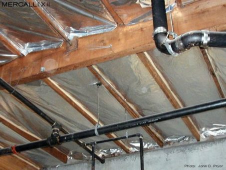
The two R&P draglines shown in this photo (located in the the 3rd and 6th sub-purlin bays from the glulam beam shown on the left) are anchored to both the first and second purlin lines in from the wall panel. As can be seen, the bearing plates associated with these R&P draglines are also located below the bottom of the sub-purlins, and will subject the purlins to cross grain bending when loaded.
M12-EX-1132
Due to the location of the ledger bolts, the R&P dragline in this photo is almost lined up on the sub-purlin line. In situations like this, the loading taken by the R&P dragline will be transferred to the diaphragm primarily through only one sub-purlin line, rather than two if the R&P dragline had been located closer to the mid-point between the two sub-purlin lines. Again, the bearing plate associated with this R&P dragline is also located below the bottom or the sub-purlins, and will subject the purlins to cross grain bending when loaded.
M12-EX-1133
Again, the bearing plate associated with this R&P dragline is located below the bottom of the sub-purlins, and will subject the purlins to cross grain bending when loaded.

