Pilaster Damage, HD’s
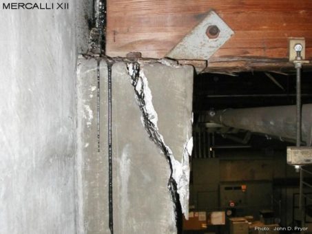
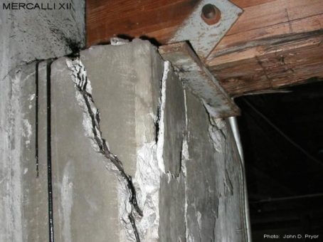
M12-EX-1081
A glulam girder supported on a pilaster at a re-entrant corner. It is not known what caused this damage, but it was possibly due to either a wind or seismic event. When this damage initially occurred it must have also caused a roof leak, as tar from the roof repair has dripped onto and into the damaged pilaster. Due to very dark conditions at this location this damaged pilaster was not discovered for some time, and only when an electrician happened to be working up in this area. At that point the glulam girder was quickly shored up. When inspected, no reinforcing could be found in the damaged area at the top of the pilaster. It should also be noted that a number of the main electrical conduits for the building were being supported by this glulam girder.
M12-EX-1082
A backup column was eventually installed at this location. The existing bracket attaching the glulam girder to the top of the pilaster was removed, and the pilaster repaired. The new attachment between the backup column and glulam girder was detailed to allow movement along the longitudinal axis of the glulam in order to mitigate future problems with the re-entrant corner at this location. If this pilaster had failed, the ensuing collapse of the glulam girder would have been catastrophic, possibly resulting in injuries or deaths, and forcing the closure of the building for many months until repairs could be made. It is interesting that an earlier roofline retrofit of the building did not address this problem.
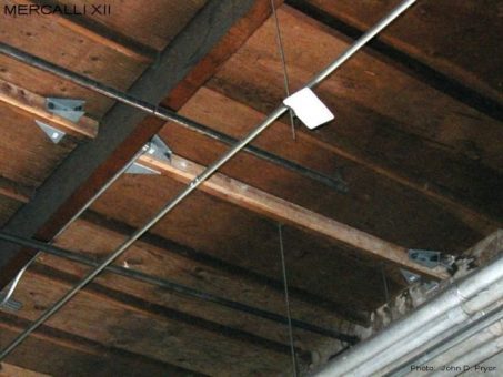
M12-EX-1083
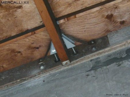
A typical timber framed dragline wall tie with paired HD5's at the wall panel and interconnecting the sub-purlins at the first purlin. Note that the existing 2x4 sub-purlins have been sistered with new 2x4's in order to meet a code provision and standards adopted since the 1994 Northridge Earthquake requiring timber framing elements associated with wall tie installations to have a minimum width of 2.5 inches. Unless specific provisions are made to either verify the existing nailing between the plywood sheathing and the sub-purlins associated with the dragline, or add new nailing (which will require that localized areas of the roofing be removed and replaced), diaphragm field nailing must be assumed. This will typically consist of 8d or 10d nails @ 12") and can greatly limit the overall capacity of a timber framed dragline wall tie system.
M12-EX-1084
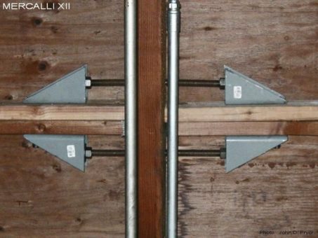
The wall tie connection of a timber framed dragstrut installation consisting of paired HD5's attached to a 2x4 sub-purlin that has been sistered with another 2x4. Even though the HD5's have not been rated for compression loading, they have been double nutted in order to provide some compression capacity. Due to the limited depth provided by the 2x4 sub-purlins, there is little adjustment that can be made when the anchors encounter reinforcing in the wall panels, and must be relocated vertically. The far side anchor appears to be an existing ledger bolts that has been coupled onto with a length of allthread rod, while the near side anchor appears to be an epoxy anchor. The capacity of anchors with dissimilar stiffness is not always additive, and can impact the overall capacity of the connection.
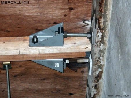
M12-EX-1085
The continuity tie connection of a timber framed dragstrut installation consisting of paired HD5's interconnecting the sistered 2x4 sub-purlins at the first purlin line in from the wall panel. As with the wall tie connection of the previous photo, the HD5's have been double nutted to provide compression capacity, even though the HD5's are not rated for compression loading. One of the problems encountered with these installations is running into the existing diaphragm nailing between the plywood sheathing and 2x4 sub-purlins when drilling the bolt holes for the HD's. This can result in misaligned and/or over-sized bolt holes.
M12-EX-1086
A paired HD5 purlin wall tie retrofit installation below a pre-existing paired strap tie installation. Even though the paired strap tie appears to have been nicely installed, it's effective capacity per current standards is limited due to it's flexibility. One of the potential problems with paired HD installations is being able to accurately drill the bolt holes without back-drilling and/or oversizing, as such connection devices were originally intended for single sided installations on the end posts of plywood shearwalls, and do not have readily available drill guides or jigs that would allow for accurately drilled bolt holes for paired installations. Over-sized bolt holes will increase the flexibility of the overall connection, which in turn will reduce the effective capacity of the overall connection.
M12-EX-1087
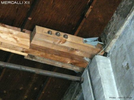
A glulam wall tie installation at a "split" pilaster condition. The paired HD5's have been padded out with double 6x6's each side of the 5.25" wide glulam beam. The 3/4" HD bolts needed for this installation had to be approximately 30" long. Not likely to be an "off the shelf" item. Given the capacity of the paired HD5 installation shown, it does not appear that the engineer considered the additional demand loads that can occur with such glulam wall tie installations due to stiffening effect associated with the pilaster. As such, the load capacity of this connection is most likely inadequate per the current code requirements and standards, which require the stiffening effect of pilasters be taken into account when assessing the demand loads required of such connections.

